It is very common for the profile of a PCB to be designed in a Mechanical CAD system such as Solidworks prior to the PCB being laid out. In the past the PCB Designer would have been handed a dimensioned drawing and tasked with recreating the board profile a second time in the PCB Design System.
The process improved over time with the transfer of the board profile from the MCAD to ECAD system using AutoCAD Drawing Interchange Format (or Drawing Exchange Format, DXF), and later Intermediate Data Format (IDF).
Currently ISO 10303‑21 or STEP format is the most versatile and popular format for transferring 3D data in both directions between Mechanical and Electronic CAD systems. There are two different STEP file formats: STEP AP203 and STEP AP214 using either .step or .stp file extensions.
The Pulsonix PCB Design package supports the import of STEP files for board profiles, and the export of the PCB assembly (board and components) to a Mechanical 3D CAD system.
In Solidworks it does not matter which plane is used for designing the PCB profile if a STEP file is output since Pulsonix, from version 8.5 build 5908 upwards, prompts the user to indicate the plane used when importing STEP files.
In Solidworks export the STEP file using File then Save As, then select a STEP file format from the “Save as type” dropdown selection. STEP AP214 has been used for these examples. The file extension for the step file should be .stp for import into Pulsonix.
The STEP file is imported into Pulsonix by using the File menu and selecting Import Design Data before selecting the STEP file. This will bring up a dialogue asking the user which plane the PCB has been designed in.

Pulsonix Import Design Data menu
PCBs designed in the Solidworks Front Plane
Pictured below is a PCB designed in the Solidworks Front Plane.
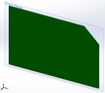
PCB Designed in the Solidworks Front Plane
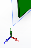
Note the direction of the x, y, z axis for the front plane shown below.

Solidworks Front Plane Axis
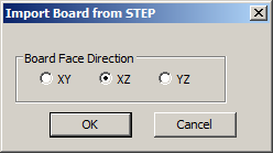
A PCB sketched in the Front Plane in Solidworks, exported to STEP AP214, and imported into Pulsonix, requires the XY Board Face Direction.

Pulsonix Import Board from STEP, Board Face Direction XY
This results in a PCB file with a closed polygon Board outline as shown below.

PCB Profile imported to Pulsonix, Front Plane XY
PCBs designed in the Solidworks Top Plane
Pictured below is a PCB designed in the Solidworks Top Plane.

PCB Profile Designed in the Solidworks Top Plane
Note the direction of the x, y, z axis for the top plane shown below.

Solidworks Top Plane Axis
A PCB sketched in the Top Plane in Solidworks, exported to STEP AP214, and imported into Pulsonix, requires the XZ Board Face Direction.
Pulsonix Import Board from STEP, Board Face Direction XZ
This results in a PCB file with a closed polygon Board outline as shown below.

PCB Profile imported to Pulsonix, Front Plane XZ
PCBs designed in the Solidworks Right Plane
Pictured below is a PCB designed in the Solidworks Right Plane.

PCB Profile designed in the Solidworks Right Plane
Note the direction of the x, y, z axis for the right plane shown below.
Solidworks Right Plane Axis
A PCB sketched in the Right Plane in Solidworks, exported to STEP AP214, and imported into Pulsonix, requires the YZ Board Face Direction.

Pulsonix Import Board from STEP, Board Face Direction YZ
This results in a PCB file with a closed polygon Board outline as shown below.

Pulsonix Imported PCB Profile in the Right Plane, YZ
